HOW ACCURATE IS THE DESIGN? (PART TWO)*
*(Part One of ‘How Accurate is the design?’ can be found on page 15 of issue 13 of the Driver Trett Digest)
Stuart Holdsworth, Hooman Baghi and Rob Gray – Structural Engineers, Diales Technical team continue their discussion as to why a lack of focus on accuracy can be a key factor in complex technical disputes.
It is implicitly understood that for engineers to achieve numerical accuracy is an absolute requirement when undertaking the design for the various parts of a structure. In this second article*, we explore this theme from the perspective of a structural engineer, and consider the potential consequences of numerical inaccuracies.
It is important to understand the significance and value of the work undertaken by the structural engineer. The cost of structural elements can account for up to 25% of a building project. The resulting consequences of such an error are likely to be out of proportion to the value of the work contributing to it, due to consequential costs such as delays, disruption, and legal fees.
There have been many claims brought against engineers as a result of errors arising from assumptions being made without a proper understanding of the risks. A lack of experience, and poor quality-control, may ensure that the error only becomes obvious at the point of failure (latent), rather than at an earlier stage in the design process, when it might have been possible to mitigate the consequences (patent).
When providing advice in these disputes, we are required to analyse and comment on the assumptions made by structural engineers, and to review the quality of the research undertaken. Sources of information for our review include structural calculations, drawings, specifications, and correspondence. In addition, we consult relevant guidance texts, such as British and European standards, which provide information on good industry practice. After an appraisal of the methods and data used for the design, it usually becomes apparent where the errors have occurred. A significant proportion of errors encountered relate to inappropriate loading assumptions, inaccuracies in geometry, and inappropriate analysis methods. These are further discussed in sections 1-3.
1. LOADING
It is unusual for structural engineers to get the scale of a common load action (such as floor loading) wrong. However, it is possible that the patterning and cycling of loads can be incorrectly determined, or that extreme load events can be miscalculated.
Depending on the use or geographical location of a structure, there may be very particular loading requirements to be considered, such as wind, earthquakes, thermal variation, or silo and liquid retaining tank loads. Wind, earthquake, or thermal loads are usually site specific, and need to be evaluated as part of the conceptual stage, early in the development of the design. This can sometimes be difficult, as information on the site conditions may be initially unavailable.
Unlike permanent or changeable loads, which are measurable and predictable, earthquake and wind loadings can be difficult to estimate. It is common practice that, due to their nature and complexity, engineers treat both of these loads with some conservatism. In the case of seismic (earthquake) loads, historic data is used to help predict the magnitude of a future seismic event. The focus of the design is to maintain the structure’s integrity during an earthquake of a greater magnitude than predicted. The design should ensure the protection of the occupants, whilst accepting that some damage may occur, such as cracking of materials or settlement of floors.
Temporary structures, either for one-off events, or as an aid to permanent works, can have unique or unusual loads applied to them. Temporary structures are the domain of designers well versed in the specific considerations required, which is an area of expertise that Diales engineers have considerable experience of. There is likely to be greater risk of failure of these structures if the loads are miscalculated, as the margins for error are usually less than for permanent structures.
There are many examples of structures that have failed during construction, or of temporary structure collapses. These incidents are often caused by a misunderstanding of the applied loads, how the structure is supported, or the intended use of temporary works. Unexpected weather conditions may also play a role. One well known example is the collapse of a church in London whilst under construction. The failure was partially attributed to the connections in a truss section being undersized; the designer had not appreciated that the truss would be supporting a greater proportion of the building during construction than in the finished state, and hence the loads it was required to resist would be greater.
2. GEOMETRY
Understanding and achieving an accurate geometric profile is an essential requirement when constructing a building. The initial geometry of a site is determined by specialist surveyors. As part of the survey, points of reference need to be accurately established and cross-referenced to generate global setting out points. Global setting out points will be defined on survey drawings, with the relevant azimuths (the relationship with the north pole) and plan locations, as a set of coordinates defined against a datum. The architect and structural engineer can then use these points to accurately locate the building and other elements within the site, using a common coordinate system.
Drafting software, such as AutoCAD or Revit, can use these points as a common reference system on drawings. It is therefore essential that the points are all referenced to the same accuracy, and correctly inputted into the drawing. The format for this information within the drawings is typically based upon numeric data using eastings, northings and an elevation, all referenced back to an Ordnance Survey datum.
If this geometric information is not transferred correctly onto drawings, it can lead to substantial errors when construction starts on site. A common example is for the positions of piles being incorrectly identified on drawings. On one project, the incorrect location of piles occurred as a result of erroneous inputting of the initial coordinate system onto the drawing by the draughtsperson. The piling rig placed the piles, positioned from details on the schedule, in a number of positions outside of the site. As the draughtsperson had similarly misplaced the site boundaries, the piles appeared to be correctly located on the drawing, until it became obvious that the foundations were being installed outside of the site perimeter. Data errors had made the issue difficult to identify before it became apparent on site.
Other inaccuracies in geometry can arise from poor communication of information between members of the design team. Building information modelling (BIM) is a useful tool for exchanging information across disciplines. However, at its current level of maturity there is still a considerable lag in data distribution. Each member of the design team works on their own model, sharing it intermittently, with the consequence that other designers could be working on out of date, incorrect information. The complexity of the information generated, as well as the varying level of each designer’s expertise in using BIM tools, can lead to difficulties in tracking changes and identifying inconsistencies.
3. ANALYSIS
A fundamental aspect of a successful structural design is choosing an appropriate analysis technique for the task at hand. This is to ensure that the structure not only functions as required, but does so with a reasonable degree of efficiency. An ‘overdesigned’ structure is undesirable, as it will be more expensive than it needs to be and may be unnecessarily complex to construct.
A recent dispute we were engaged on related to the analysis of a portal frame warehouse. The engineer had analysed the structure using ‘elastic’ techniques, which are generally used if the deflection of the structure is a critical concern. As there were no movement sensitive finishes to the inside or outside of the building, a ‘plastic’ analysis could have been employed, which – in simple terms – allows the structure to deform. Figures 1 and 2 illustrate the deformations calculated for the same portal frame warehouse structure using these techniques.
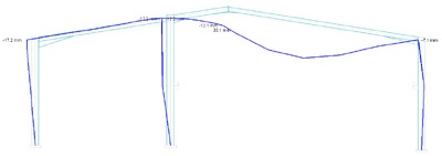
Fig.1 - Plastic analysis, showing deformation of a frame
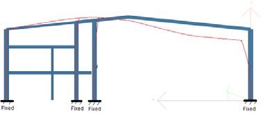
Fig. 2 - Elastic analysis, showing deformation of a frame
As a result of this analysis, the steel sections were designed to be of a larger size than if a ‘plastic’ analysis had been used, resulting in an inefficient design that exceeded the projected cost of the structural frame.
Similarly, structural designers often produce a ‘worst-case’ design for a particular structural element, and apply these conditions to other (or all) structural elements. This approach is common for complex steel framed buildings with a large number of elements, that would require a considerable amount of computational time to individually analyse. Although this approach speeds up the design process, it creates an inefficient overall design. That said, simplifying the number of sections used, and ensuring that sections of similar sizes and different grades are avoided, usually saves money and is less likely to result in an inconsistently fabricated steel structure. Fabricators will usually ensure that the most production efficient design is used.
IN CONCLUSION
Numerical accuracy, achieved by the structural engineer, is critical to the successful execution of a project. The range and depth of experience of an engineering expert ensures that their technical expertise is sufficient to understand and evaluate areas in which inaccuracies have occurred, and to follow the thought process of the project’s structural engineer. It is evident from our investigations of numerous claims brought against structural engineers, that avoiding such errors requires them to carefully consider the potential risks of any assumptions made, and to have a sound understanding of the tools at their disposal.
In addition, the importance of quality control cannot be overstated, as it will help to identify inaccuracies at an early stage. Although computer software allows results to be obtained quickly and cheaply, a ‘sense check’ must also be carried out to identify any obvious errors, such as incorrect data input, that can be corrected before serious consequences develop.
Download here